Last update : May 31, 2016
DICOM (Digital Imaging and Communications in Medicine) is a software integration standard that is used in Medical Imaging. It’s success relies on the ability of modern imaging equipment, manufactured by many different vendors, to seamlessly collaborate and integrate together. Medical imaging equipments are called Imaging Modalities and include X-Rays, Ultrasound (US), Computed Radiography (CR), Computed Tomography (CT), Magnetic Resonance Imaging (MRI), Endoscopie (ES), and others.
DICOM standard
The Digital Imaging and Communications in Medicine (DICOM) standard (now ISO 12052) was first conceived by the American College of Radiology (ACR) and the National Electrical Manufacturers Association (NEMA) in 1983. DICOM changed the face of clinical medicin. The release 3 of the standard was published in 1993 and since then an updated version is edited every year. The current version is PS3-2016b. The DICOM standard is often considered to be be very complicated or tricky, the publication is now more than 3.000 pages long. A list of the 18 parts (parts 9 and 13 were retired) of the DICOM standard is shown below :
- Part 3.1 : Introduction and Overview
- Part 3.2: Conformance
- Part 3.3: Information Object Definitions
- Part 3.4: Service Class Specifications
- Part 3.5: Data Structures and Encoding
- Part 3.6: Data Dictionary
- Part 3.7: Message Exchange
- Part 3.8: Network Communication Support for Message Exchange
- Part 3.10: Media Storage and File Format for Media Interchange
- Part 3.11: Media Storage Application Profiles
- Part 3.12: Media Formats and Physical Media for Media Interchange
- Part 3.14: Grayscale Standard Display Function
- Part 3.15: Security and System Management Profiles
- Part 3.16: Content Mapping Resource
- Part 3.17: Explanatory Information
- Part 3.18: Web Access to DICOM Persistent Objects (WADO)
- Part 3.19: Application Hosting
- Part 3.20 : Transformation of DICOM to and from HL7 Standards
The DICOM standard is promoted by IHE (Integrating the Healthcare Enterprise), an initiative by healthcare professionals and industry to improve the way computer systems in healthcare share information.
DICOM core
The DICOM core is a file format and a networking protocol.
All medical images are saved in DICOM format, but DICOM files contain more than just images. Every DICOM file holds informations about the patient, the context of the study, the type of equipment used etc.
All medical imaging equipments that are connected to a health network (hospital, …) use the DICOM network protocol to exchange informations, mainly images and binary data. This protocol allows to search for medical images in an archive and to download them to a doctor’s workstation in order to display them.
DICOM Objects
Developers knowing object oriented programming should be familiar with DICOM objects. Patients, medical devices, clinical studies etc are entities in the real world. DICOM has abstract definitions for these entities, called DICOM Information Entities (IEs). DICOM uses a data model with SOP (Service Object Pair) classes and Information Object Definitions (IODs) to handle these entities in the DICOM world. For example, a patient IOD has attributes for patient’s name, ID, date of birth, weight, sex and all other clinically relevant patient related informations.
The DICOM data model defines four object levels :
- Patient
- Study
- Series & Equipment
- Instance (image)
The name instance, instead of image, was introduced some years ago, because there are now DICOM objects at the fourth level which are not images. These objects are sometimes called DICOM P10 instances with reference to the PS3.10 DICOM standard.
Each of the levels can contain several sub-levels. The following figure shows the DICOM information hierarchy :

DICOM Information Hierarchy
One patient may have multiple studies at different times, each study may include several series with one or more instances.
DICOM differentiates between normalized and composite IODs. A normalized IOD represent a single real-world entity with inherent attributes. Composite IODs are mixtures of several real-world entities.
The DICOM Information Modules are used to group attributes into logical and structured units. Modules can be mandatory, conditional, optional or user-defined. DICOM specifies for each IE the modules it should include. For example, the patient IE should include the patient module, the specimen identification module and the clinical trial subject module. All DICOM objects must include the SOP common module and the four modules of the data model. All DICOM instances that are images must include the Image module.
The attributes of an IOD are encoded as Data Elements.
Let’s summarize the chapter about DICOM objects in a few other words :
- The DICOM data model is made of Information Entities (IEs)
- The classes of the DICOM data model are called SOP classes
- SOP is a pair of a DICOM object and a DICOM service
- SOP classes are defined by IODs
- IODs are collections of modules
- Modules are collections of data elements
- Data elements collections refer to an Information Entity (IE)
DICOM Data Elements
DICOM objects are encoded in binary form as sequential lists of attributes, called Data Elements. Every data element has :
- a tag to uniquely define the element and its proprieties. A tag is comprised of a 16-bit Group number and a 16-bit Element number. Data elements that are related to another have the same Group number.
- an optional Value Representation (VR), represented as two character code, to define the data type (examples : UI = Unique identifier, CS = coded string, US = unsigned short, …). The VR is called explicit when available. The data type is also specified by the tag and VR is omitted (implicit VR) if determined by the negotiated Transfer Syntax.
- a length to specify the size of the value field. DICOM values length are always even. Values with a single data are padded by a space in the case of strings and by a null (0x0) in the case of binary types. DICOM lengths are specified with 16 bit if VR is explicit and with 32 bit if VR is implicit. The value filed length can be undefined (FFFFFFFFH).
- a value field with the corresponding informations. If the length of the value field is undefined, a sequence delimitation item marks its end.
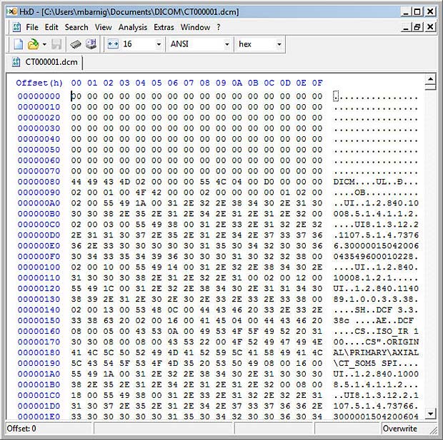
DICOM File displayed in Hexeditor
There are thousands of different DICOM data elements with a well specified meaning. The names of the data elements are referenced in a DICOM dictionary. Here are some examples :
| Tag Group Number | Tag Element Number | Element or Attribute Name |
| 0010 | 0010 | Patient’s Name |
| 0010 | 0030 | Patient’s Birthday |
| 0020 | 0011 | Series Number |
| 0028 | 0010 | Image Rows |
| 0028 | 0011 | Image Columns |
The data elements are sorted sequentially by ascending tag number. It’s possible to define additional elements, called private elements, to add specific informations, but it is recommended to use existing elements whenever possible. Standard DICOM data elements have an even group number and private data elements have an odd group number.
Secondary Capture Image Object
The simplest DICOM object is the Secondary Capture (SC) Image. It has a minimal set of data elements that a DICOM application needs in order to display and archive a medical image. It’s not related to a particular medical image device. The following table shows the mandatory modules for the Secondary Capture Image Object :
| Information Entity (IE) | Module | Reference |
| Patient | Patient | C.7.1.1 |
| Study | General Study | C.7.2.1 |
| Series | General Series | C.7.3.1 |
| Equipment | SC Equipment | C.8.6.1 |
| Instance (Image) | General Image | C.7.6.1 |
| Image | Image Pixel | C.7.6.3 |
| Image | SC Image | C.8.6.2 |
| Image | SOP Common | C.12.1 |
There are only two modules that are specific to SC (Secondary Capture), the other modules are common and shared by many IODs. Every module is rather large and includes lots of data elements, but luckily most of these data elements are optional. In the DICOM standard the modules are marked with a type column :
- value 1 : data element is mandatory and must be set
- value 2 : data element is mandatory, but can be null
- value 3. data element is optional
Values 1 and 2 can also been marked as c for conditional.
The following table shows the mandatory data elements for the Secondary Capture Image Object :
| Attribute Name | Tag | Type |
| Patient’s Name | (0010, 0010) | 2 |
| Patient ID | (0010, 0020) | 2 |
| Patient’s Birth Date | (0010,0030) | 2 |
| Patient’s Sex | (0010, 0040) | 2 |
| Study Instance UID | (0020, 000D) | 1 |
| Study Date | (0008, 0020) | 2 |
| Study Time | (0008, 0030) | 2 |
| Referring Physician’s Name | (0008, 0090) | 2 |
| Study ID | (0020, 0010) | 2 |
| Accession Number | (0008, 0050) | 2 |
| Modality | (0008, 0060) | 1 |
| Series Instance UID | (0020, 000E) | 1 |
| Series Number | (0020, 0011) | 2 |
| Laterality | (0020, 0060) | 2C |
| Conversion Type | (0008, 0064) | 1 |
| Instance Number | (0020, 0013) | 2 |
| Patient Orientation | (0020, 0020) | 2C |
| Samples per Pixel | (0028, 0002) | 1 |
| Photometric Interpretation | (0028, 0004) | 1 |
| Rows | (0028, 0010) | 1 |
| Columns | (0028, 0011) | 1 |
| Bits Allocated | (0028, 0100) | 1 |
| Bits Stored | (0028, 0101) | 1 |
| High Bit | (0028, 0102) | 1 |
| Pixel Representation | 0028, 0103) | 1 |
| Pixel Data | (7FE0, 0010) | 1C |
| Planar Configuration | (0028, 0006) | 1C |
| SOP Class UID | (0008, 0016) | 1 |
| SOP Instance UID | (0008, 0018) | 1 |
| Specific Character Set | (0008, 0005) | 1C |
Unique Identifiers
DICOM makes extensive use of Unique Identifiers (UIDs). Almost every entity has a UID, with the exception of the patient (patients are identified with their name and their ID). DICOM defines a mechanism in order to make sure UIDs are globally unique. Every DICOM application should acquire a root UID that is used as a prefix for the UIDs it creates.
Usually the Study Instance UID is provided through a DICOM service called Modality Worklist. The Series UID and the SOP Instance UID are always generated by the application.
DICOM Networking Protocol
The following figure shows the typical medical imaging workflow.
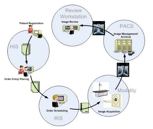
Medical Imaging Workflow
The workflow begins when the patient gets registered in the Hospital Information System (HIS). An Electronic Medical Record (EMR) is generated for the new patient. A medical procedure, for example an X-Ray of the thorax, is ordered and placed into the Radiology Information System (RIS). The RIS generates a study scheduled and sends an HL7-event to a HL7-DICOM gateway. The gateway sends the study scheduled event to the Picture Archiving and Communication System (PACS) to prefetch previous exams of the patient. When the patient arrives at the modality (X-Ray in this example), the technologist requests the Modality Worklist (MWL : a sort of task manager) and updates the RIS. The acquired images are forwarded to the PACS where they are checked, stored and forwarded to the review workstation of the radiologist. The radiologist views the study images and reports possible pathologies.
The Modality Worklist is combined with a Modality Performed Procedure Step (MPPS) that allows the Modality to report the task status and to take ownership over the task. Associated to MPPS are the Requested Procedure (RP), the Requested Procedure Description, the Requested Procedure Code Sequence and the Scheduled Procedure Step (SPS). MPPS is the checkmark for MWL.
The main DICOM nodes in this workflow are the Modality, the PACS and the Workstation. DICOM’s network communication is based on the ISO/OSI model. The entities (nodes) in the network are specified with the following parameters :
- Application Entity (AE) Title : max 16 characters, case sensitive;
it’s a sort of alias for the combination of IP address and port number - IP address
- Port number
With the parameters of the source and the target AE, we can start a per-to-peer session called Association. This is the first step of a DICOM network communication. The second step is exchanging DICOM commands. Most problems in DICOM communications are related to failing association negotiations. Errors are reported in the DICOM log.
The calling AE sends an Association Request to the target (called) AE. It’s a description of the application, its capabilities and its intentions in this session (presentation context). The called AE checks the request and sends back an Association Response, confirming what can and can’t be done. If its doesn’t match, the calling AE can reject the association. An important parameter is the Max PDU Size, an application level packet that says how big is the buffer consumed for the request. Some calling application entities uses buffer sizes too large for the called application entity; the result can be a crash due to a buffer overflow. In case of none-response by the called AE, the request will timeout.
A DICOM service related to the exchange step is Storage Commitment (SCM) that lets you verify if files sent to a PACS where indeed stored correctly. The result is sent using the N-EVENT-REPORT command.
DICOM services are used for communication within an entity and between entities. A service is built on top of a set of DICOM Message Service Elements (DIM-SEs) adapted to normalized and composite objects. DIM-SEs are paired : when a device issues a command, the receiver responds accordingly.
DICOM services are referred to as Service Classes. A Service Class Provider (SCP) provides a service, a Service Class User (SCU) uses a service. A device can be an SCP, an SCU or both. The following table shows the main DIM-SE’s : commands with a C-prefix are composite and those with a N-prefix are normalized.
| C-ECHO | sort of application level ping to verify a connection; this service is mandatory for all AEs |
| C-FIND | inquiries about information object instances |
| C-STORE | allows one AE to send a DICOM object to another AE |
| C-GET | transmission of an information object instance |
| C-MOVE | similar to C-GET, but receiver is usually not the command initiator |
| C-CANCEL | interrupt a command |
| N-CREATE | creation of an information object |
| N-GET | retrieval of information object attribute value |
| N-SET | specification of an information object |
| N-DELETE | Deletion of an information object |
| N-EVENT-REPORT | result from SCM |
A fundamental service implemented by every workstation is the Query / Retrieve (Q / R) task. The query is done with C-FIND. The keys to search are Patient Name, Patient ID, Accession Number, Study Description, Study Date, Modality, … The Retrieve is done with C-MOVE and C-STORE commands.
DICOM Serialization = Transfer Syntax
To transmit DICOM objects through a network or to save them into a file, they must be serialized. The DICOM Transfer Syntax defines how this is be done. There are 3 basic transfer syntaxes presented in the next table :
| UID | Transfer Syntax | Notes |
| 1.2.840.10008.1.2.1 | Little Endian Explicit (LEE) | stores data little-end first, explicit VR |
| 1.2.840.10008.1.2.2 | Big Endian Explicit (BEE) | stores data big-end first, explicit VR |
| 1.2.840.10008.1.2 | Little Endian Implicit (LEI) | stores data little-end first, implicit VR |
A complete list is shown in my post DICOM TransferSyntaxUID.
The transfer syntax specifies 3 points :
- if VRs are explicit
- if the low byte of muti-byte data is the first serialized or the last serialized
- if pixel data is compressed and when yes, what compression algorithm is used
LEI is the default Transfer Syntax which shall be supported by every conformant DICOM Implementation. Compressed pixel data transfer syntax are always explicit VR little Endian. The following compression methods can be used :
- jpeg
- jpeg lossless
- jpeg 2000
- RLE
- JPIP
- MPEG2
- MPEG4
If DICOM objects are serialized into files, there are additional informations to provide :
- a preamble of 132 bytes, where the first 128 bytes are null and the last 4 bytes are the DICOM magic number DICM.
- a file meta header consisting of data elements of group 0002, written in Little Endian Explicit
- an element (0002, 0010) with the Transfer Syntax UID that is used for all the data elements other than group 0002.
Group 0002 data elements are strictly used for files and must be removed before sending DICOM objects over the network.
If DICOM files are saved on a standard CD / DVD, they should have a file named DICOMDIR in its root directory. DICOMDIR is a DICOM object listing the paths to the files stored on the media. The file names of these files should be capital alphanumeric up to 8 characters with no suffix. An example of naming conventions is shown hereafter :
- directory PAxxx for every patient (xxx = 001, 002, …)
- inside PAxxx a directory STyyy for every (yyy = 001, 002, …)
- inside STyyy a directory SEzzz for every series (zzz = 001, 002, …)
- inside SEzzz a DICOM file MODwwwww for every instance
(MOD = CT, CR, …; wwwww = 00001, 00002, …)
DICOM files stored in the cloud or on a non-DICOM media have the suffix .dcm.
Pixel Data
Because imaging is the heart of DICOM, we will deal with the bits of images in a specific chapter called pixel data. The data elements of the pixel module have group number 0028 and are responsible for describing how to read the image pixels. The next table shows the different data elements :
| Tag | VR | Description |
| (0028, 0002) | US | Samples PerPixel : number of color channels; grey = 1 |
| (0028, 0004) | CS | PhotometricInterpretation : MONOCHROME1 -> 0 = white ; MONOCHROME2 -> 0 = black ; YBR_FULL -> YCbCr space |
| (0028, 0006) | US | PlanarConfiguration : 0 = interlaced color pixels ; 1 = separated pixels |
| (0028, 0008) | IS | NumberOfFrames : number of frames in the image; multi-frame >1 |
| (0028, 0010) | US | Rows : height of the frame |
| (0028, 0011) | US | Columns : width of the frame |
| (0028, 0100) | US | BitsAllocated : space allocated in the buffer (usually 16) |
| (0028, 0101) | US | BitsStored : how many allocated space is used (in CT usually 12) |
| (0028, 0102) | US | HighBit : the bit number of the last bit used (in CT usually 11) |
| (0028, 0103) | US | PixelRepresentation : unsigned = 0 (default) ; signed = 1 |
| (0028, 1050) | DS | WindowCenter : |
| (0028, 1051) | DS | WindowWidth : |
| (0028, 1052) | DS | RescaleIntercept : |
| (0028, 1053) | DS | RescaleSlope : |
| (7FE0, 0010) | OB | Image Pixel Data : (for CT -> VR = OW : other word) |
The group number of the image data element is 7FE0 to be sure that this element is the last in the DICOM object. It is usually a very long data element and can be easily skipped if we want to read only the headers.
The Image Plane Module defines the direction of the image with reference to the patient body. It also gives the dimensions of the pixels in mm. The corresponding data element has tag 0020, 0037. DICOM defines a Reference Coordinate System (RCS) of the patient body.
X-direction is from Right to Left in the Axial (transversal) Cut. Y-direction is from Front (Anterior) to Back (Posterior) in the Sagittal Cut. Z-direction is from feet to head in Coronal Cut. The following letters are assigned to the ends of each direction :
- [R] – Right – X decreases
- [L] – Left – X increases
- [A] – Anterior – Y decreases
- [P] – Posterior – Y increases
- [F] – Feet – Z decreases
- [H] – Head – Z increases
These letters are usually displayed on the sides of a DICOM viewer. If the patient is in an oblique position, there can be letter combinations like [PR] for Posterior Right or [ALH] for Anterior Left Head.
onformance Statement
DICOM Conformance Statement
DICOM requires that a Conformance Statement must be written for each device or program claiming to be DICOM conformant. The format and content of a Conformance Statement is defined in the standard itself.
Links
Additional informations about the DICOM standard are available at the following websites :
- DICOM is easy, by Roni Zaharia
- DICOM Web Viewer, Bachelor Thesis by Michael Kaserer
- The DICOM standard, by Center for Advanced Brain Imaging (CABI)
- DICOM Support for Compression: More than JPEG
- DICOM Library : free online DICOM file sharing service
- GDCM: DICOM vu de l’intérieur, par Mathieu Malaterre
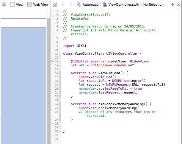
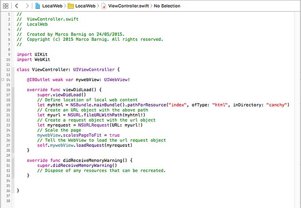
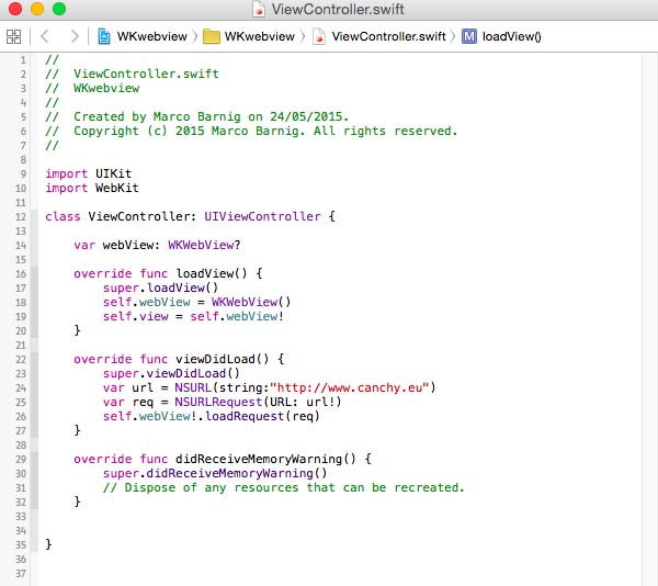

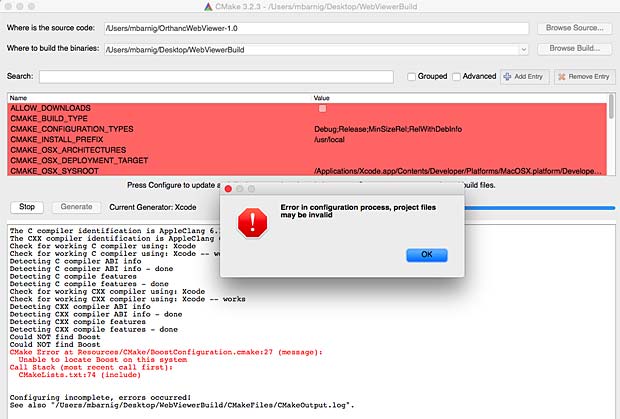
 The primary mechanism of the

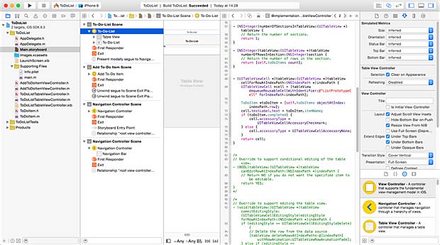
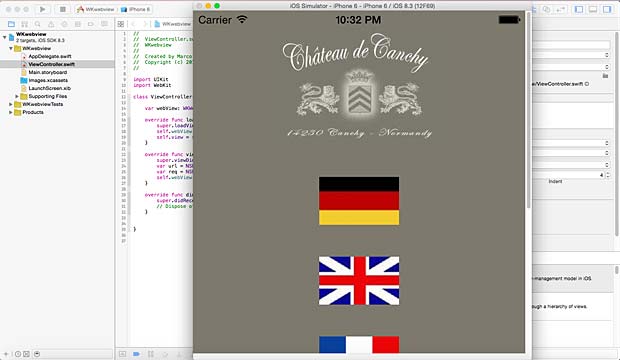
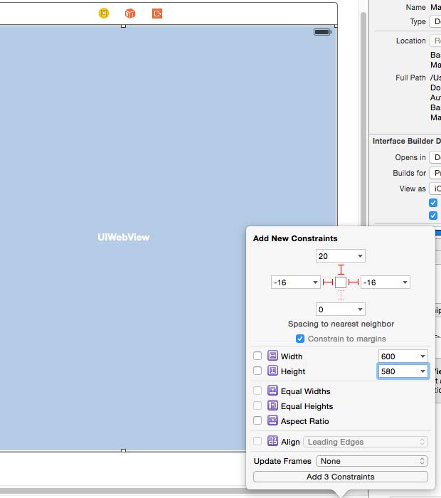
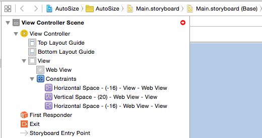
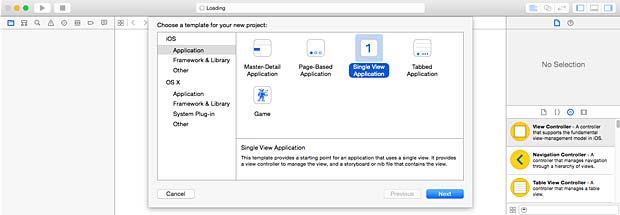
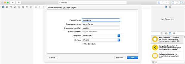
 To tell the Xcode IDE which configuration to use during a particular build is determined by a scheme. A scheme unites a target with a build configuration. A new project commes by default with a single scheme named after the project.