3D Game Engines

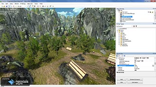
3D Game Engines provide game designers with the framework to create games. The core functions of 3D game engines are the following :

3D Game Engines

3D Game Engines

  • rendering
  • animation
  • scripting
  • sound generation
  • collision detection (physics engine)
  • networking
  • threading
  • memory management
  • artificial intelligence


The following 3D game engines are relevant in the context of embodied virtual agents :

Other renowned 3D game engines are listed hereafter :

Some 3D renderers are sometimes listed as 3D game engines, for example :

More informations about 3D game engines are available at the following links :

BioBlender visualization

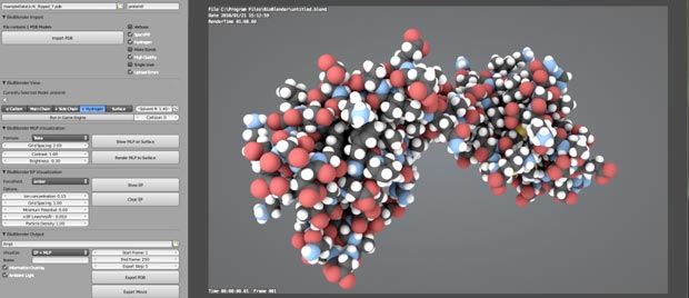
BioBlender is a software package built on the open-source 3D modeling software Blender. BioBlender version 1.0 for Windows and Linux was released on July 12, 2013. The first beta version of BioBlender (v 0.1) was presented in September 2010.

BioBlender

BioBlender

BioBlender is the result of a collaboration, driven by the SciVis group at the Institute of Clinical Physiology (CNR) in Pisa, Italy, between scientists of different disciplines (biology, chemistry, physics, computer sciences) and artists, using Blender in a rigorous but at the same time creative way.

With BioBlender users can handle proteins in the 3D space, displaying their surface in a photorealistic way, and elaborate protein movements on the basis of known conformations. Scientists all over the world study proteins at atomic level and deposit information in the public repository Protein Data Bank, where each molecule is described as the list of its atoms and their 3D coordinates.

BioBlender can be used for:

  • import and visualize Protein Data Bank (PDB) files (The PDB file format is a textual file format describing the three dimensional structures of molecules held in the Protein Data Bank)
  • simulate molecular dynamics and optimize protein motion
  • visualize complex protein surface properties  (e.g. MLP and EP surface properties)

A BioBlender tutorial was published by Raluca Andrei, Mike Chen Pan and Monica Zoppè, in the BlenderArt magazine N.31 in December 2010.

3D character rigging and inverse kinematics

Pinocchio 2007, by Ilya Baran and Jovan Popovic

Rigging (skeletal animation) is a process used in computer animation, particularly in the animation of characters, to efficiently mimic real world skeletal systems for animation purposes. Characters are represented in two parts: a surface representation used to draw the character (called skin or mesh) and a hierarchical set of interconnected bones (called the skeleton or rig) used to animate (pose and keyframe) the mesh.

This rigging technique is used by creating a series of bones to form skeletons. Each bone in the skeleton is responsible for deforming and animating a part of the character mesh and has a three dimensional transformation (position, scale and orientation) The bones  form a hierarchy, the skeleton.

Usually the animator is assisted through inverse kinematics and other goal-oriented techniques. The benefit of rigging is that an animation can be defined by simple movements of the bones, instead of vertex by vertex changes. The drawback of rigging is that it does not provide realistic muscle movement and skin motion.

Manual rigging to specify its internal skeletal structure and to define how the input motion deforms its surface is a tedious process. Most 3D modeling & animation packages used by professionals provide inbuilt automatic rigging and skinning algorithms. An example is the BlenRig System for Blender.

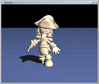
An experimental auto rigging and animation tool called Pinocchio was presented in 2007 at SIGGRAPH by Ilya Baran and Jovan Popovic from the Computer Science and Artificial Intelligence Laboratory at the Massachusetts Institute of Technology (MIT). The corresponding paper “Automatic Rigging and Animation of 3D Characters” was published in the ACM proceedings of SIGGRAPH. The source files, binaries for Windows and test meshes are available from the Pinocchio project page at MIT.

A commercial standalone automatic rigging tool, called Jimmy|RIG, was created by Origami Digital LLC, to allow people to quickly apply motion capture data to their characters without the tedious process of painting weights and setting up a skeleton. Different software versions are available, a Lite version starts at 150 $US.

A web-based automatic rigging solution is offered by Mixamo which provides the first premium quality 3D character animation experience entirely online.

The following list shows some links to videos related to automatic rigging :


Biovision Hierarchy (BVH) Format and MoCap data for Character Animation

bvhacker version 1.8.0.6, by D. Wooldridge

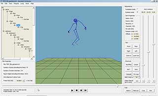
The Biovision Hierarchy (BVH) character animation file format was developed by Biovision, a defunct motion capture services company. BVH provides skeleton hierarchy information as well as motion data. The BVH format is an ASCII file that is used to import rotational joint data. It is currently one of the most popular motion data formats, and has been widely adopted by the animation community, probably because of its simple specifications.

Most 3D modeling & animation packages used by professionals provide an inbuilt BVH editor. This contribution mainly focus on tools and motion data accessible to animation hobbyists.

A list of some commercial and free BVH tools is shown below :

  • bvhacker : free bvh file editing tool ideally suited for final preparation of bvh files for upload to Second Life
  • BVH Helper : a suite of Python tools to aid the import of BVH files into Poser
  • BVHplay : a free, open-source BVH animation player
  • Life Forms Studio 5 : the most powerful character-animation package in its price-range
  • SimFonIA : innovative plugin for 3D animation for  SketchUp
  • iClone 5 : real-time 3D animation
  • bvh player for iPad : bvh files can be imported by email or iTunes

Next comes a list of commercial and free BVH animation data :

Additional informations about character animation are available at the following links :

Polygon Cruncher and other 3D mesh optimizing tools

Among 3D mesh optimizing tools, Polygon Cruncher, developed by Manuel Jouglet, owner of the french company Mootools, is the most renowned program. Polygon Cruncher reduces the number of polygons of  3D objects without changing their appearance. You keep all details, materials, textures, vertex colors and normals, even at high optimization ratio. Polygon Cruncher uses an exceptional algorithm developed since more than 10 years and gives incomparable results. It is really simple to use and has been chosen by major 3D companies.

The latest version of Polygon Cruncher is 10.02 released on May 25, 2012. Polygon Cruncher exists in different version: StandAlone which includes Maya files support, plugin for 3D Photo Browser, plugin for 3DS Max / 3ds Max Design and plugin for Lightwave Modeler. A free SDK for developers, offering Polygon Cruncher optimization features through a C++ library is also available. The price for a full single licence is 129$.

Another famous mesh optimizing tool (open source) is Meshlab.

Andy Davies, a Hampshire-based (UK) 3D Artist, administrator/instructor of www.eat3d.com, created a video in 2009 showing a comparison between Polygon Cruncher and Meshlab.

Other mesh optimizing tools are listed hereafter :

PCL : Point Cloud Library

documentation segmentation on the pointclouds.org website

A point cloud is a data structure used to represent a collection of multi-dimensional points and is commonly used to represent three-dimensional data. In a 3D point cloud, the points usually represent the X, Y, and Z geometric coordinates of an underlying sampled surface. When color information is present, the point cloud becomes 4D.

Point clouds are most often created by 3D scanners. Point clouds can be directly rendered and inspected, but generally they are not directly usable in most 3D applications, and therefore are usually converted to polygon or triangle mesh models, NURBS surface models, or CAD models through a process commonly referred to as surface reconstruction.

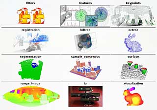
Here comes in the Point Cloud Library (PCL), a standalone, large scale, open project for 3D point cloud processing. The PCL framework contains numerous state-of-the art algorithms including filtering, feature estimation, surface reconstruction, registration, model fitting and segmentation, as well as higher level tools for performing mapping and object recognition. PCL is released under the terms of the BSD license and it’s free for commercial and research use.

The PCL website provides a blog, a news, media and download section and a great documentation with tutorials, descriptions, API’s and advanced topics about 3D point clouds.

One example of a PCL project is the open source version of KinectFusion.


MeshMixer, Sculptris, zBrush and 3D-Coat

meshmixer version 07 update 4

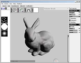
Meshmixer is an experimental easy-to-use mesh cleanup/composition/sculpting 3D modeling tool developed by Ryan Schmidt, who is a Research Scientist at Autodesk Research in Toronto, Canada. Ryan is also the author of the sketch-based implicit surface modeler ShapeShop. Meshmixer is now part of Autodesk. The current version of Meshmixer is 07, update 4, released on May 18, 2012. An up-to-date documentation is not yet available.

Meshmixer is often compared to Sculptris, a sculpting tool that Tomas Pettersson has been developing since early December 2009. Sculptris was picked up by Pixologic when Tomas Petterson joined this company in 2010. Sculptris is still available for free at the Pixologic website and the skills you learn with Sculptris can be directly translated to ZBrush, the award winning and most widely-used digital sculpting application in today’s market. The models that you create with Sculptris can even be sent to ZBrush with the click of a button using the GoZ™ functionality.

Another commercial digital sculpting program is 3D-Coat from Pilgway. It was designed to create free-form organic and hard surfaced 3D models from scratch.


netfabb Studio Basic for 3D printing

netfabb Sudio Basic 4.9.1

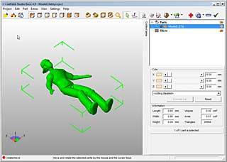
The real revolution of 3D printing is coming from inexpensive 3D printers and from online services that will fabricate the designs you upload. The free netfabb Studio Basic software helps to create 3D designs for printing easily. It offers all the functionality needed for creating build data out of an STL file : STL display and inspection, hole closing and mesh repair, part placement and orientation on a platform, part slicing and export.

The current version is 4.0.1. A detailed documentation is available at the Wiki of the website.

The free netfabb Studio software can be upgraded to a professional version : netfabb Studio Professional. Priced at a very affordable level, netfabb Studio Professional is a full range mesh edit, repair, analysis and slicing software for a number of 3D input and output formats.

There is also a free portable app called netfabb mobile for Android or iPhone that allows you to view .STL files on your mobile device.

KinectFusion

Microsoft Kinect Fusion Demo Picture

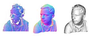
Microsofts research project KinectFusion investigates techniques to track the 6DOF (six degrees of freedom) position of handheld depth sensing cameras, such as Kinect, as they move through space and perform high quality 3D surface reconstructions for interaction. The technique is shown on the KinectFusion demo video on Youtube.

Two research papers, co-authored by more than 10 researchers across Microsoft Research and three universities, have been published :

Until now, Microsoft has not yet released the code of Kinect Fusion. Based on the scientific paper that describes the algorithms in some detail, an open source implementation of KinectFusion has been developed by the project team of the Point Cloud Library (PCL). Jasper Brekelmans from the Netherlands, Technical Director at Motek and developer of the Brekel Kinect Tool, compiled a binary version of the PCL solution (KinFu). He provides also an all-in-one OpenNI Kinect auto driver installer with all needed files to run his application or the Kinect Fusion program.

Another outstanding program to construct 3D models in realtime with a Kinect (or with another depht sensing device), based on the ideas of KinectFusion, is the project ReconstructMe developped by Christoph Heindl of PROFACTOR GmbH.

Additional informations about the KinectFusion project are available at the following links :

MeshLab 3D software

Last update : September 15, 2014
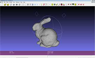
MeshLab

Meshlab 1.3.1

MeshLab is an advanced 3D mesh processing software system which is well known in the more technical fields of 3D development and data handling. As free and open-source software it is used both as a complete package, and also as libraries powering other software. MeshLab is available for most platforms. The MeshLab system started in late 2005 as a part of the FGT course of the Computer Science department of University of Pisa and most of the code of the first versions was written by a handful of willing students. The official website is meshlab.sourceforge.net, the latest version is V1.3.3 released on April 2, 2014 and available at the following link.

The lead developer of Meshlab and main designer of the VCG library is Paolo Cignoni.

MeshLab for iOS (former name MeshPad) is an advanced 3D model viewer for iOS. MeshLab is also available for Android. It is recommended by ReconstructMe to process the Kinect scan files.

MeshLab user guide

One of the weak points of MeshLab is the lack of documentation. I created a quick user guide based on the video tutorials available at Youtube.

Project

A project assembles meshes, textures, and rasters. The main screen of MeshLab shows the model, the mesh name, the number of vertices and faces, the camera field of view (FOV) and the number of frames per second (FPS). A mesh is imported in the menu File>Import Mesh into a new project.

Navigation

The navigation is based on the concept of a trackball. Pressing the left mouse button and dragging the trackball allows to rotate the model. Pressing the control key and dragging the model allows to pan the model. Pressing the shift key and dragging the model up or down allows to zoom the model in or out. Zooming can also be done with the mouse wheel. The field of view of the camera is changed by pressing the shift key and using the mouse wheel (FOV : ortho / 6.2 – 90). By double clicking a point of the model the center of the trackball will be set to this point. By pressing control+h you can reset the trackball center to its original position. The menu Help>on screen quick help (Function key F1) shows all the navigation commands.

Lighting

Lighting can be switched on and off in the Menu Render>Lighting>Light on/off or with the yellow Light icon. By pressing control+shift and dragging the model the light direction can be changed. The direction is shown with yellow lines. With the menu Render>Lighting>Double Side Lighting you select a right and left light source. The light color can be changed in the menu Tools>Options. The parameters fancyBLightDiffuseColor and fancyBLightDiffuseColor allow to select different colors for both lights. The effect is enabled with the menu Render>Lighting>Fancy Lighting. The Tools>Options menu allows also to change the top, background, ambient, specular, diffuse and area color, or to reset them to the original colors.

Feedback

If a second model is loaded, the on-screen information is updated and the total number of vertices and faces is also shown. A pop-up window shows the two models, the selected one is marked yellow. A feedback about the actions and filters applied is displayed in the lower part of this window. Attributes and other informations like the number of selected faces are also shown on-screen.

Preview and Help

MeshLab has no undo function, but most filters have a preview function which can be checked before application. Filters have also an individual help button which provides useful information about its features and parameters.

Selection

Selection of faces is an important feature of the program. It is activated by the menu Edit>Select faces in a rectangular region or with the corresponding icon. Press the alt key to select only the visible faces on the model. Press the control key to add selections or the shift key to do substractions.You can combine the alt key with the other keys to work only on the visible faces. To change the position of the model press the Esc key to show the trackball. Press again the Esc key to return to the selection mode.

Selection of vertexes works the same way as for faces. Use the menu Edit>Select Vertexes or the corresponding icon to activate this state. The same is true for the menu Edit>Select connected components in a region which allows to deal with isolated geometries. You can also use the brush (menu Edit>Z-painting) to select faces. Painting is different from the selection tools : only the visible faces are selected and all painted areas are added. The menu Filters>Selection offers numerous other selection tools (by color, quality, edges, length, …).

Snapshots

Use the menu File>Save snapshot or the camera icon to take pictures of the displayed model. There are several options : transparent background, screen multiplier to get high resolution images, tiled images, snap all layers.

Decimation

To simplify a mesh use the filter Remeshing, Simplification and Reconstruction>Quadric Edge Collapse Decimation.

Alignment