netfabb Studio Basic for 3D printing

netfabb Sudio Basic 4.9.1

The real revolution of 3D printing is coming from inexpensive 3D printers and from online services that will fabricate the designs you upload. The free netfabb Studio Basic software helps to create 3D designs for printing easily. It offers all the functionality needed for creating build data out of an STL file : STL display and inspection, hole closing and mesh repair, part placement and orientation on a platform, part slicing and export.

The current version is 4.0.1. A detailed documentation is available at the Wiki of the website.

The free netfabb Studio software can be upgraded to a professional version : netfabb Studio Professional. Priced at a very affordable level, netfabb Studio Professional is a full range mesh edit, repair, analysis and slicing software for a number of 3D input and output formats.

There is also a free portable app called netfabb mobile for Android or iPhone that allows you to view .STL files on your mobile device.

KinectFusion

Microsoft Kinect Fusion Demo Picture

Microsofts research project KinectFusion investigates techniques to track the 6DOF (six degrees of freedom) position of handheld depth sensing cameras, such as Kinect, as they move through space and perform high quality 3D surface reconstructions for interaction. The technique is shown on the KinectFusion demo video on Youtube.

Two research papers, co-authored by more than 10 researchers across Microsoft Research and three universities, have been published :

Until now, Microsoft has not yet released the code of Kinect Fusion. Based on the scientific paper that describes the algorithms in some detail, an open source implementation of KinectFusion has been developed by the project team of the Point Cloud Library (PCL). Jasper Brekelmans from the Netherlands, Technical Director at Motek and developer of the Brekel Kinect Tool, compiled a binary version of the PCL solution (KinFu). He provides also an all-in-one OpenNI Kinect auto driver installer with all needed files to run his application or the Kinect Fusion program.

Another outstanding program to construct 3D models in realtime with a Kinect (or with another depht sensing device), based on the ideas of KinectFusion, is the project ReconstructMe developped by Christoph Heindl of PROFACTOR GmbH.

Additional informations about the KinectFusion project are available at the following links :

MeshLab 3D software

Last update : September 15, 2014

MeshLab

Meshlab 1.3.1

MeshLab is an advanced 3D mesh processing software system which is well known in the more technical fields of 3D development and data handling. As free and open-source software it is used both as a complete package, and also as libraries powering other software. MeshLab is available for most platforms. The MeshLab system started in late 2005 as a part of the FGT course of the Computer Science department of University of Pisa and most of the code of the first versions was written by a handful of willing students. The official website is meshlab.sourceforge.net, the latest version is V1.3.3 released on April 2, 2014 and available at the following link.

The lead developer of Meshlab and main designer of the VCG library is Paolo Cignoni.

MeshLab for iOS (former name MeshPad) is an advanced 3D model viewer for iOS. MeshLab is also available for Android. It is recommended by ReconstructMe to process the Kinect scan files.

MeshLab user guide

One of the weak points of MeshLab is the lack of documentation. I created a quick user guide based on the video tutorials available at Youtube.

Project

A project assembles meshes, textures, and rasters. The main screen of MeshLab shows the model, the mesh name, the number of vertices and faces, the camera field of view (FOV) and the number of frames per second (FPS). A mesh is imported in the menu File>Import Mesh into a new project.

Navigation

The navigation is based on the concept of a trackball. Pressing the left mouse button and dragging the trackball allows to rotate the model. Pressing the control key and dragging the model allows to pan the model. Pressing the shift key and dragging the model up or down allows to zoom the model in or out. Zooming can also be done with the mouse wheel. The field of view of the camera is changed by pressing the shift key and using the mouse wheel (FOV : ortho / 6.2 – 90). By double clicking a point of the model the center of the trackball will be set to this point. By pressing control+h you can reset the trackball center to its original position. The menu Help>on screen quick help (Function key F1) shows all the navigation commands.

Lighting

Lighting can be switched on and off in the Menu Render>Lighting>Light on/off or with the yellow Light icon. By pressing control+shift and dragging the model the light direction can be changed. The direction is shown with yellow lines. With the menu Render>Lighting>Double Side Lighting you select a right and left light source. The light color can be changed in the menu Tools>Options. The parameters fancyBLightDiffuseColor and fancyBLightDiffuseColor allow to select different colors for both lights. The effect is enabled with the menu Render>Lighting>Fancy Lighting. The Tools>Options menu allows also to change the top, background, ambient, specular, diffuse and area color, or to reset them to the original colors.

Feedback

If a second model is loaded, the on-screen information is updated and the total number of vertices and faces is also shown. A pop-up window shows the two models, the selected one is marked yellow. A feedback about the actions and filters applied is displayed in the lower part of this window. Attributes and other informations like the number of selected faces are also shown on-screen.

Preview and Help

MeshLab has no undo function, but most filters have a preview function which can be checked before application. Filters have also an individual help button which provides useful information about its features and parameters.

Selection

Selection of faces is an important feature of the program. It is activated by the menu Edit>Select faces in a rectangular region or with the corresponding icon. Press the alt key to select only the visible faces on the model. Press the control key to add selections or the shift key to do substractions.You can combine the alt key with the other keys to work only on the visible faces. To change the position of the model press the Esc key to show the trackball. Press again the Esc key to return to the selection mode.

Selection of vertexes works the same way as for faces. Use the menu Edit>Select Vertexes or the corresponding icon to activate this state. The same is true for the menu Edit>Select connected components in a region which allows to deal with isolated geometries. You can also use the brush (menu Edit>Z-painting) to select faces. Painting is different from the selection tools : only the visible faces are selected and all painted areas are added. The menu Filters>Selection offers numerous other selection tools (by color, quality, edges, length, …).

Snapshots

Use the menu File>Save snapshot or the camera icon to take pictures of the displayed model. There are several options : transparent background, screen multiplier to get high resolution images, tiled images, snap all layers.

Decimation

To simplify a mesh use the filter Remeshing, Simplification and Reconstruction>Quadric Edge Collapse Decimation.

Alignment


Adobe AIR 3.2

Adobe Integrated Runtime (AIR) is a cross-platform runtime environment developed by Adobe Systems for building Rich Internet Applications (RIA) using Adobe Flash, Adobe Flex, HTML, CSS and Javascript, that can be run as desktop applications or on mobiles, including iOS devices.

Adobe AIR requires applications to be packaged, digitally signed, and installed on the user’s local file system. This provides access to local storage and file systems, while browser-deployed applications are more limited in where and how data can be accessed and stored. Adobe AIR internally uses Adobe Flash Player as the runtime environment, and ActionScript 3 as the sole programming language. Flash applications must specifically be built for the Adobe AIR runtime in order to utilize the additional features provided.

Adobe AIR 1.0 was released on February 25, 2008, after a public pre-release in 2007. Adobe Air 3.2 was released on March 28 2012, it’s the first version supporting Stage3D on iOS devives.

Stage3D in Flash

Adobe Flash Player 11 introduced a new architecture for hardware-accelerated graphics (processed by GPU = graphics processing unit) rendering called Stage3D (codename Molehill). This set of 3D APIs brings 3D to the Adobe Flash Platform. The book Adobe Flash Player 11 Stage3D (Molehill) Game Programming Beginner’s Guide, written by Christer Kaitila, shows you how to make your very own next-generation 3D games in Flash. Christer Kaitila is the curator of a popular news website called www.videogamecoder.com which syndicates news from hundreds of other game developer blogs.

The following frameworks and libraries are available for Stage3D :

Flare3D Studio and Mixamo’s online animation service have been integrated into a smooth workflow, allowing Flash developers to easily leverage the Stage 3D API and its capabilities. Stage3D content can be embedded in AIR 3.2 to deploy applications on mobiles, including iOS devices.

The Stage3D API includes a low level shading language, called AGAL (Adobe Graphics Assembly Language). Shaders are programs that run on the GPU (Graphics Processing Unit).

Tutorials and additional informations about Stage3D and related frameworks are listed below :

David and Nextengine 3D Scanners

DAVID Laserscanner Software

DAVID-laserscanner is a very low-cost system for contact-free scanning of 3d objects. The only hardware requirements are a simple commercial hand-held laser and a standard camera.

A free edition of the David Laserscanner (current version 3.2.0.2830 released on March 2, 2012), with limited saving,  including a trial version of the David Shapefusion software, is available at the website. The unlimited pro-version costs 329 EUR. DAVID-Shapefusion is more than just an ordinary stitching tool, it allows a convenient alignment and combination of 3D scans from different viewing directions.

The David-Laserscanner website provides a download, gallery, forum, wiki, FAQ, references an user guide section. The lasershop offers cameras, lasers, software and accessories, from a starterkit (499 EUR) up to a structured light kit (1773,10 EUR).

A comparison of the David – Laserscanner with the worlds most popular 3D scanner, the NextEngine priced at 2.995 US $, was done in 2009 in the David – Laserscanner forum. In the meantime the speed of the David – Laserscanner has been increased with the structured light solution.


ReconstructMe 3D Scanner and Youworld

Last update : May 29, 2012

Youworld by Mark Florquin ; rendered 3D scans of family and friends ; 18 May 2012

ReconstructMe is an intuitive 3D realtime reconstruction system offering unique features :

  • Multiple 3D sensor support (Microsoft Kinect, ASUS Xtion Pro Live
  • Offline reconstruction from existing file streams
  • Resuming reconstructions at any point in time
  • Surface export to common 3D file formats such as .stl or .obj

ReconstructMe is free for non-commercial use and is being developed and maintained by enthusiastic software engineers at PROFACTOR GmbH. The initiator of ReconstructMe and one of its main contributors is Christoph Heindl who owns the personal blog cheind.wordpress.com.

There are countless applications of the ReconstructMe technology, such as scanning objects to duplicate with a 3D printer, importing yourself into a video game, …

The official ReconstructMe Homepage launched in january 2012 has a blog, download, help, media, purchase and legal section to provide all necessary informations to start using this outstanding technology. The current version of the software is 0.6.0-405 released end May 2012. The commercial version was launched on May 29, 2012; the price for a single seat license is 360 EUR.

Mark Florquin, a photographer from Belgium, is the first artist to use the Kinect & ReconstructMe technology to scan his family and friends and to render photos of these 3D models. He created an own world (Youworld)  to publish the results on his website.

Windows folders, junctions and libraries

Microsoft first introduced the My Documents folder in Windows 95 OEM Service Release 2, as a standard location for storing user-created files. The folder was displayed on the user’s desktop, but located under the root of the hard drive where Windows was installed. In Microsoft 98 the special folders My Music and My Pictures were added, later the My Videos folder by installing the Windows Media Player 10 or 11.

In Windows XP the “My Documents folder” was set up in the user’s profile directory \Documents and Settings\[user name]\My Documents\ (alias %USERPROFILE%\My Documents\. as a special folder, which is presented to the user through an interface as an abstract concept, instead of an absolute folder path. This makes it possible for an application to ask the operating system where an appropriate location for certain kinds of files can be found, regardless of what version or language of operating system is being used.

The same was true for My Music, My Pictures and My Videos.

Windows Vista renamed the “My XXX folders” simply as “Documents, Music, Pictures, Videos” and moved them under the user’s profile directory (C:\Users\[user name]\ alias %USERPROFILE%\). To enable backward operability (compatibility) with legacy applications, the concept of NTFS junction points was introduced. A junction folder is a sort of shortcut and displayed with an curved arrow in the icon. When clicking on a junction folder in Windows Explorer, an “Acces denied” message is usually displayed.

Windows 7 keeped the same location and mecanisms, but reintroduced the “My” prefix in the user’s profile directory. Windows 7 launched also the concept of libraries to make it easier to find, work with, and organize files scattered across a PC or a network. Libraries are user-defined collections of content. To assemble a photo album for example, snapshots can be saved physically in different locations, but with a library they show up in a single window.

Windows 7 comes with one main library called “Libraries”, containing four default libraries : documents, music, pictures, and videos. They can be extended, customized and shared with others with just a few clicks. Up to 50 folders can be included in one library. Every library has a default save location. Each library contains two physical file locations, the user’s personal folder(s) and the public folder. Only locations that are indexed by Windows 7 can be added to a library.

A library consists of the following parts :

  • General library information
  • Library properties
  • Library locations

More informations about folders, junctions and libraries are available at the following links :

Text (term, word, tag) Clouds

Examples of tag clouds

A text, term, word or tag cloud, also called a weighted list in visual design, is a representation for text data to show the most prominent terms and their relative prominence. These clouds are typically used to depict keyword metadata (tags) on websites. The importance of each tag is shown with font size or color.

When used as website navigation aids, the terms are hyperlinked to items associated with the tag. Compared to conventional navigation, tag clouds can provide visitors with an instant illustration of the main topics, giving a very specific and precise orientation of the site’s content. Examples and good practice for tag clouds, with a gallery, have been published in 2007 by Vitaly Friedman, editor-in-chief of the Smashing Magazine.

There is a number of on-line tools available which help designers to create tag clouds automatically. A few links are listed hereafter :

It’s also easy to generate hand-made tag clouds by creating the required number of css-classes and applying them to the HTML code.

Example :
CSS :

div {text-align:left; font-family:Arial; background-color:white; border: 1px solid silver}
.tag1 {color:red; font-size:12px}
.tag2 {color:blue; font-size:14px}
.tag3 {color:green; font-size:18px}

HTML:

<div>
<a href="url">Term ABC</a>
<a href="url">Term defgh</a>
<a href="url">Term 1234</a>
<a href="url">Term xyz xyz</a>
</div>

Additional informations and tools about tag clouds are available at the following links :

Sphero : a robotic ball and 3D controller

Last update : November 30, 2013

Sphero by Orbotix

Sphero by Orbotix

Today I received my Sphero from Orbotix. Sphero is a smart robot inside an opaque, high-impact, waterproof polycarbonate shell. It’s charged with a cable-free induction charger. It glows in thousands of colors and can move (roll) up to 1 meter per second. Sphero connects with Bluetooth to iOS and Android tablets and smartphones.

The Sphero_Ball can be used as a game for adults, kids and pets or as an 3D controller for various applications. There are over 20 free apps and some paid apps available. A Full API and Mobile SDK for iOS and Android allows developers to create additional aps. I particularly enjoy to play Last Fish with the SpheroBall as 3D controller.
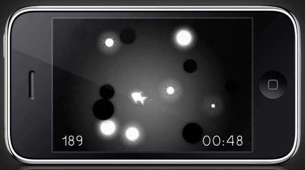
Last Fish

Last Fish

Orbotix was founded in 2010 by Ian Bernstein and Adam Wilson.

In August 2013, Orbotix launched Sphero 2 which is twice as fast, three times as brightly lit and much smarter than the first generation ball, which is now called Sphero Original. Sphero 2 is compatible with up to 25 different applications and games, along with the standard Sphero_App’s.

Sphero user guide

When the ball flashes red three times, his battery is low and he needs charging. The ball is charged by popping him with the heavy side down in the induction charger. To find his heavy side, place him on a hard surface like a table. Sphero will naturally settle with this sweet spot at the bottom. The charger will blink blue when charging begins. After about 3 hours, the blue light becomes solid and the ball is ready to roll. If the ball is awake when charging starts, he confirms the correct charging with a rainbow cycle of  colors before going to sleep..

A quick double shake of the Sphero wakes the ball up, setting its light show going – after which it will be available to connect over Bluetooth.The ball can be put to sleep with the basic Sphero app. It falls asleep when it is inactive during a few minutes.

You need to pair your device with the ball on Bluetooth in the settings before starting an iOS or Android app. When Sphero is paired with a device, it is not visible for other devices. You must unpair it with the current device, if you want to use it with another device. When the unpairing is not possible (for instance if the current device is not available), it’s necessary to reset Sphero by placing him in the charger and running a strong magnet around his circumference. A video demonstrates this technique.

Sphero Development

Orbotix supports developers by providing a blog, a forum, documentation, resources, official SDK’s (iOS, Android, Unity3D, Windows 8.1, Augmented Reality (AR), …) and unofficial SDK’s (Node, Arduino, Python, Ruby, …) on its Sphero Developer Center.

Links to additional informations about Sphero are listed below :

I updated my Sphero firmware  a first time on May 9, 2013 (software version 2.1.2 : firmware version 1.45; Bootloader version 1.7;  Sphero identifier : 00066644024C). A second update was done on November 30, 2013 with App version 3.1.21; firmware version is now 1.49.