Introduction
Today most computers, graphic cards and monitors can display 16-bit, 24-bit, 32-bit or even 48-bit color depth. The color quality can be selected in the control center of the graphic (video) card.
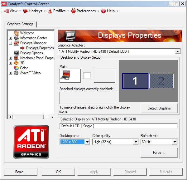
Example : ATI Radeon Control Center Window
8-bit-color
In 8-bit color graphics each pixel is represented by one byte, the maximum number of colors that can be displayed at any one time is 256. There are two forms of 8-bit color graphics. The most common uses a separate palette of 256 colors, where each of the 256 entries in the palette map is given red, green, and blue values. The other form is where the 8 bits directly describe red, green, and blue values, typically with 3 bits for red, 3 bits for green and 2 bits for blue.
16-bit color
With 16-bit color, also called High color, one of the bits of the two bytes is set aside for an alpha channel and the remaining 15 bits are split between the red, green, and blue components, allowing 32,768 possible colors for each pixel. When all 16 bits are used, one of the components (usually green) gets an extra bit, allowing 64 levels of intensity for that component, and a total of 65.536 available colors.
24-bit color
Using 24-bit color, also called True color, computers and monitors can display as many as 16.777.215 different color combinations.
32-bit color
Like 24-bit color, 32-bit color supports 16.777.215 colors with an additional alpha channel to create more convincing gradients, shadows, and transparencies. With the alpha channel 32-bit color supports 4.294.967.296 color combinations.
48-bit color
Systems displaying a billion or more colors are called Deep Color. In digital images, 48 bits per pixel, or 16 bits per each color channel (red, green and blue), is used for accurate processing. For the human eye, it is almost impossible to see any difference between such an image and a 24-bit image.
CLUT
A colour look-up table (CLUT) is a mechanism used to transform a range of input colours into another range of colours. It can be a hardware device built into an imaging system or a software function built into an image processing application.
HDR
High-dynamic-range imaging (HDR) is a set of techniques used in imaging and photography to reproduce a greater dynamic range of luminosity than is possible with standard digital imaging or photographic techniques. The aim is to present the human eye with a similar range of luminance as that which, through the visual system, is familiar in everyday life.
Pixel Image

PixelImage 8×8
To dive into the Image Manipulations with Javascript, we will use the Pixel Image shown left which has 8 x 8 pixels and a color depth of 1 bit. The bit value 0 is associated to the color white, 1 means black. We see later that in real systems the colors are inverted (1 = white, 0 = black). In the next steps we will look how to display this image in a browser with HTML5 and javascript.
The following table shows the pixel data for the image. I used the MathIsFun website to do the binary to hexadecimal and decimal conversion.
| rows |
column bits |
hexadecimal |
decimal |
| 1 |
01111110 |
7E |
126 |
| 2 |
10000001 |
81 |
129 |
| 3 |
10100101 |
A5 |
165 |
| 4 |
10000001 |
81 |
129 |
| 5 |
10011001 |
99 |
153 |
| 6 |
10000001 |
81 |
129 |
| 7 |
11100111 |
E7 |
231 |
| 8 |
00111100 |
3C |
60 |
We can now use the following code to draw the pixels on a canvas :
<body>
<canvas id="pixelboard" width="512" height="512"></canvas>
<script>
var myCanvas = document.getElementById("pixelboard");
var myContext = myCanvas.getContext("2d");
myContext.fillStyle = "silver";
myContext.fillRect(0, 0, myCanvas.width, myCanvas.height);
myContext.fillStyle = "black";
// here are the pixel data for the 8 rows
var pixelData = [126, 129, 165, 129, 153, 129, 231, 60];
for (i = 0; i < pixelData.length; i++ ) {
 var base2 = (pixelData[i]).toString(2);
 var p = 7;
 // set pixels in canvas from right to left
 for (j = (base2.length-1); j >= 0; j-- ) {
 if (base2[j] == 1) {
 myContext.fillRect(p * 64, i * 64, 64, 64);
 } // end if
 p--;
 } // end base2
} // end pixelData
</script>
</body>
Click this PixelData link to see it working. The image is stored in 8 bytes.
PNG Image
To draw the picture in the original size of 8×8 pixels, we change the canvas size
<canvas id="pixelboard" width="8" height="8"></canvas>
and the code line in the inner loop as follows
myContext.fillRect(p, i, 1, 1);
Click this PixelData link to see it working.
We can save the small Pixel image in the browser with a right mouse click as canvas.png file. The size of this PNG image file is 108 bytes, 100 bytes more than the size of the image stored in our javascript.Thats a lot of overhead. Sort od design overkill !
Let’s have a look inside this file with an HexEditor (HxD from Maël Hörz).
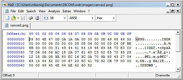
Anatomy of a small PNG Image File
We can identify the words PNG, IHDR, IDAT and IEND. The PNG format is specified by the W3C. A lite description is available at the FileFormat.Info website. PNG (pronounced “ping”) is a bitmap file format used to transmit and store bitmapped images. PNG supports the capability of storing up to 16 bits (gray-scale) or 48 bits (truecolor) per pixel, and up to 16 bits of alpha data. It handles the progressive display of image data and the storage of gamma, transparency and textual information, and it uses an efficient and lossless form of data compression.
A PNG format file consists of an 8-byte identification signature followed by chunks of data :
- Header chunk (IHDR) : the header chunk (13 bytes) contains basic information about the image data and must appear as the first chunk, and there must only be one header chunk in a PNG file.
- Palette chunk (PLTE) : the palette chunk stores the colormap data associated with the image data. This chunk is present only if the image data uses a color palette and must appear before the image data chunk.
- Image data chunk (IDAT) : the image data chunk stores the actual image data, and multiple image data chunks may occur in a data stream and must be stored in contiguous order.
- Image trailer chunk (IEND) : the image trailer chunk must be the final chunk and marks the end of the PNG file or data stream.
- Optional chunks are called ancillary chunks (examples : background, gamma, histogram, transparency, …) and can be inserted before or after the image data chunks. Ten ancillary chunks have been defined in the first PNG version.
Each chunk has the following structure, each chunk has an overhead of 12 bytes :
- DataLength (4 bytes)
- ChunkType (4 bytes)
- Data (number of bytes specified in DataLength)
- CRC-32 (4 bytes)
The IHDR chunk specifies the following parameters in the 13 data bytes :
- ImageWidth in pixels (4 bytes)
- ImageHeight in pixels (4 bytes)
- BitDepth (1 byte)
- ColorType (1 byte)
- Compression (1 byte)
- Filter (1 byte)
- Interlace (1 byte)
An analysis of our PixelData PNG image provides the following results :
- ImageWidth in pixels : 00 00 00 08 (big-endian) > 8 pixels
- ImageHeight in pixels : 00 00 00 08 (big-endian) > 8 pixels
- BitDepth : 08 > 8 bit
- ColorType : 06 > Truecolour with alpha (RGBA)
- Compression : 00 > default = deflate
- Filter : 00 > default = adaptive filtering
- Interlace : 00 > no
- ImageDataLength : 00 00 00 31 (big-endian) > 49 bytes
In the HexEditor we see that the 49 bytes of deflated image data are :
18 95 63 38 70 E0 C0 7F 06 06 06 AC 18 2A 07 61
60 C3 50 85 70 95 28 12 18 0A 08 9A 80 EC 16 9C
0A 70 9A 80 43 27 04 63 15 44 52 0C 00 67 20 8C 41
The image data is zlib-compressed using the deflate algorithm. zlib is specified in RFC1950, deflate is specified in RFC1951. The process is sufficient complex to not do it manually. We can use the javascript pako.js library to decompress the data block. This library was designed by Vitaly Puzrin and Andrey Tupitsin.
Here comes the code :
<!DOCTYPE HTML>
<html>
<head>
 <meta charset="utf-8">
 <title>Inflate byte block of PNG image pixel data with pako.js</title>
 <script type="text/javascript" src="js/pako.js"></script>
</head>
<body>
<h1>Inflate byte block of PNG image pixel data with pako.js</h1>
<div id="main"></div>
 <script type="text/javascript" >
// enter datastream as array
var hexData = [0x18, 0x95, 0x63, 0x38, 0x70, 0xE0, 0xC0, 0x7F, 0x06, 0x06,
0x06, 0xAC, 0x18, 0x2A, 0x07, 0x61, 0x60, 0xC3, 0x50, 0x85, 0x70, 0x95, 0x28,
0x12, 0x18, 0x0A, 0x08, 0x9A, 0x80, 0xEC, 0x16, 0x9C, 0x0A, 0x70, 0x9A, 0x80,
0x43, 0x27, 0x04, 0x63, 0x15, 0x44, 0x52, 0x0C, 0x00, 0x67, 0x20, 0x8C, 0x41];
 // Pako inflate
 var inflateData = pako.inflate(hexData);
// output inflated data
var output = "<p>The lenght of the inflated data sequence is : "
+ inflateData.length + "bytes.<br/>";
 for (i = 0 ; i < 8; i++) {
 for (j = 0 ; j < 33; j++) {
 console.log((i * 33) + j);
 output+= decimalToHexString(inflateData[(i * 33) + j]) + " ";
 } // end for loop j
 output+= "<br/>";
 } // end for loop i
 output+= "</p>";
 element = document.getElementById("main");
 element.innerHTML = output;
 function decimalToHexString(number)
{ if (number < 0)
 { number = 0xFFFFFFFF + number + 1; }
 return number.toString(16).toUpperCase();
}
</script>
</body>
</html>
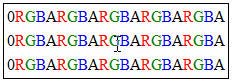
Byte sequence in PNG image rows
The byte sequence of pixel data stored in PNG images is shown in the left figure.
In our case we have 8 rows with 8 * 4 bytes (RGBA) plus one null byte, giving a total of 8 * 33 = 264 bytes.
Click the inflate link to see the result of the inflate process. The sequence length is really 264 bytes and the structure of the PNG format is visible in the output.
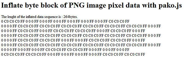
inflating PNG image data
The RGB hexadecimal values C0 generate grey (white) pixels, the values 0 generate black pixels. The alpha channel is always transparent (hex FF).
Synthesize a PNG image
To synthesize a minimal PNG image with monochrome PixelData, we modify the original canvas.png data as follows :
1. The signature does not change, the bytes in hexadecimal format are :
89 50 4E 47 0D 0A 1A 0A
2. In the header we set the bit depth to 1 (mono-chrome) and the color type to 0 (gray-scale). We get the following byte sequence in hexadecimal format :
00 00 00 0D 49 48 44 52 00 00 00 08 00 00 00 08 01 00 00 00 00
We have several possibilities to calculate the new CRC32 checksum over the header name and the new data :
CRC32 calculation with desktop and online tool
Here comes the code for the javascript CRC32 calculation :
<!DOCTYPE HTML>
<html>
<head>
 <meta charset="utf-8">
 <title>Calculate checksum crc32 with SheetJS/js-crc32
of canvas.png chunks</title>
 <script type="text/javascript" src="js/SheetJS_crc32.js"></script>
</head>
<body>
<h1>Calculate checksum crc32 with SheetJS/js-crc32 of canvas.png chunks</h1>
<div id="main"></div>
 <script type="text/javascript" >
 // calculate crc32 over chunk name and data
// enter datastream as hexadecimal numbers
var charData = [0x49, 0x48, 0x44, 0x52, 0x00, 0x00, 0x00, 0x08, 0x00, 0x00,
0x00, 0x08, 0x01, 0x00, 0x00, 0x00, 0x00];
var myCRC32 = CRC32.buf(charData);
var crc = decimalToHexString(myCRC32);
var output = "<p>Here is the signed 32 bit number of the CRC32 : "
+ myCRC32 + "<br/>Here is the hexadecimal value of the CRC32 : "
+ crc + "</p>";
 element = document.getElementById("main");
 element.innerHTML = output;
 function decimalToHexString(number)
{  if (number < 0)
   { number = 0xFFFFFFFF + number + 1 }
   return number.toString(16).toUpperCase();
} // end function
 </script>
</body>
</html>
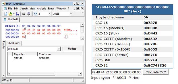
Click this CRC32 link to see it working. The checksum to add to the IHDR chunk is EC 74 83 26.
Now we tackle the IDAT chunk. We have 8 rows for the PixelData, starting each with a NullByte (filter), followed by 1 byte in each row for the monochrome pixels. That makes a total of 16 bytes. The data length in hexadecial format is 10. We use 1 for black and 0 for white, giving us the following byte sequence :
00 7E 00 81 00 A5 00 81 00 99 00 81 00 E7 00 3C
This byte sequence is deflated with the Pako.js library with the following script :
<!DOCTYPE HTML>
<html>
<head>
 <meta charset="utf-8">
 <title>Deflate byte block of PNG image pixel data with pako.js</title>
 <script type="text/javascript" src="js/pako.js"></script>
</head>
<body>
<h1>Deflate byte block of PNG image pixel data with pako.js</h1>
<div id="main"></div>
 <script type="text/javascript" >
 // enter datastream as numbers
var charData = [0x00, 0x7E, 0x00, 0x81, 0x00, 0xA5, 0x00, 0x81, 0x00, 0x99,
0x00, 0x81, 0x00, 0xE7, 0x00, 0x3C];
 // Pako deflate
 var deflateData = pako.deflate(charData);
 var output = "<p>The length of the deflated data sequence is : "
+ deflateData.length + " bytes.<br/>";
 for (i = 0; i < deflateData.length; i++) {
 output+= decimalToHexString(deflateData[i]) + " ";
 } // end for loop i
 output+= "</p>";
 element = document.getElementById("main");
 element.innerHTML = output;
 function decimalToHexString(number)
{ if (number < 0)
 { number = 0xFFFFFFFF + number + 1; }
 return number.toString(16).toUpperCase();
}
</script>
</body>
</html>
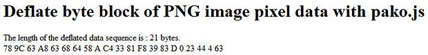
Click this deflate link to see the result. The length of the deflated sequence has 21 bytes (hex : 15) and is longer than the original sequence.That happens with very short image sequences.
deflating PNG image data
There are possibilities to minify the deflated sequence lenght, but this is not our goal. There are several blogs and posts dealing with smallest possible png images.
The last step is the calculation of the CRC32 checksum, same procedure as above. The following crc32 link shows the 4 byte hexadecimal number : EC 01 89 73.
The final byte sequence for the IDAT chunk is displayed hereafter :
00 00 00 15 49 44 41 54 78 9C 63 A8 63 68 64 58 0A C4 33 81 F8 39 83 0D 00 23
44 04 63 EC 01 89 73
3. The IEND chunk remains unchanged and has no associated data :
00 00 00 00 49 45 4E 44 AE 42 60 82
To create and display this synthetic PNG image, we copy all the hexadecimal data in our HexEditor and save it as mysynth.png file. To check that the format is right, we can use the pngcheck tool or load the image in Photoshop. It works.
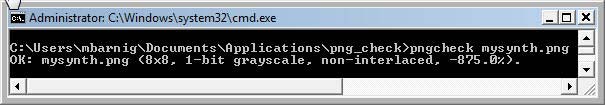
Analayse file mysynth.png with pngcheck.exe

Open file mysynth.png in Photoshop
Display the PNG image in the Browser
The typical HTML code to display an image in a web browser is
<img src="url" alt="abcde" width="xxx" height="yyy" />
The src attribute specifies the URI (uniform resource identifier) of the image. The most common form of an URI is an URL (uniform resource locator) that is frequently referred as a web address. URIs identify and URLs locate. Every URL is also an URI, but there are URIs which are not URLs.
The URI syntax consists of a URI scheme name (such as “http”, “ftp”, “mailto” or “file”) followed by a colon character, and then by a scheme-specific part. An example of an URI which is not an URL is a dataURI, for example
data:,Hello%20World
The data URI scheme is a URI scheme that provides a way to include data in-line in web pages as if they were external resources. This technique allows normally separate elements such as images and style sheets to be fetched in a single HTTP request rather than multiple HTTP requests, which can be more efficient.
We will use the dataURI to display our synthesized PNG image in a web browser without saving it to an external source. The data URI scheme is defined in RFC 2397 of IETF. URI’s are character strings, therefore we must convert (encode) the image data to ASCII text. The most common conversion is base64, another method is percent encoding.
There are several possibilities to encode our image data in base64 :
Here comes the code for the javascript btoa() conversion :
<!DOCTYPE HTML>
<html>
<head>
 <meta charset="utf-8">
 <title>Display mysynth.png with dataURI</title>
 </head>
<body>
<h1>Display mysynth.png with dataURI</h1>
<div id="main"></div>
 <script type="text/javascript" >
var signature = [0x89, 0x50, 0x4E, 0x47, 0x0D, 0x0A, 0x1A, 0x0A];
var ihdr = [0x00, 0x00, 0x00, 0x0D, 0x49, 0x48, 0x44, 0x52, 0x00, 0x00,
0x00, 0x08, 0x00, 0x00, 0x00, 0x08, 0x01, 0x00, 0x00, 0x00, 0x00, 0xEC,
0x74, 0x83, 0x26];
var idat = [0x00, 0x00, 0x00, 0x15, 0x49, 0x44, 0x41, 0x54, 0x78, 0x9C,
0x63, 0xA8, 0x63, 0x68, 0x64, 0x58, 0x0A, 0xC4, 0x33, 0x81, 0xF8, 0x39,
0x83, 0x0D, 0x00,
0x23, 0x44, 0x04, 0x63, 0xEC, 0x01, 0x89, 0x73];
var iend = [0x00, 0x00, 0x00, 0x00, 0x49, 0x45, 0x4E, 0x44, 0xAE, 0x42,
0x60, 0x82];
var mysynthPNG = signature.concat(ihdr).concat(idat).concat(iend);
var imageStringBase64 = btoa(String.fromCharCode.apply(null, mysynthPNG));
var mysynthImg=document.createElement("img");
mysynthImg.setAttribute('src', 'data:image/png;base64,' + imageStringBase64);
mysynthImg.setAttribute('alt', 'mysynthPNG');
mysynthImg.setAttribute('height', '8px');
mysynthImg.setAttribute('width', '8px');
document.body.appendChild(mysynthImg);
</script>
</body>
</html>
Click the following base64 link to see the result. The pixel colors are inverted, 1 is white and 0 is black.
Links
The following list provides links to websites with additional informations about image pixel manipulations :